RL Series combinations
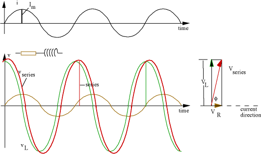
In an RL series circuit, the voltage across the inductor is
aheadof the current by 90°, and the inductive reactance, as we saw before, is X
L = ωL. The resulting v(t) plots and phasor diagram look like this.

It is straightforward to use Pythagoras' law to obtain the series impedance and trigonometry to obtain the phase. We shall not, however, spend much time on RL circuits, for three reasons. First, it makes a good exercise for you to do it yourself. Second, RL circuits are used much less than RC circuits. This is because inductors are always* too big, too expensive and the wrong value, a proposition you can check by looking at an electronics catalogue. If you can use a circuit involving any number of Rs, Cs, transistors, integrated circuits etc to replace an inductor, one usually does. The third reason why we don't look closely at RL circuits on this site is that you can simply look at RLC circuits (below) and omit the phasors and terms for the capacitance.* Exceptions occur at high frequencies (~GHz) where only small value Ls are required to get substantial ωL. In such circuits, one makes an inductor by twisting copper wire around a pencil and adjusts its value by squeezing it with the fingers.

