Now let's put a resistor, capacitor and inductor in series. At any given time, the voltage across the three components in series, vseries(t), is the sum of these:
vseries(t) = vR(t) + vL(t) + vC(t),
The current i(t) we shall keep sinusoidal, as before. The voltage across the resistor, vR(t), is in phase with the current. That across the inductor, vL(t), is 90° ahead and that across the capacitor, vC(t), is 90° behind.
Once again, the time-dependent voltages v(t) add up at any time, but the RMS voltages V do not simply add up. Once again they can be added by phasorsrepresenting the three sinusoidal voltages. Again, let's 'freeze' it in time for the purposes of the addition, which we do in the graphic below. Once more, be careful to distinguish v and V.
Look at the phasor diagram: The voltage across the ideal inductor is antiparallel to that of the capacitor, so the total reactive voltage (the voltage which is 90° ahead of the current) is VL - VC, so Pythagoras now gives us:
V2series = V2R + (VL - VC)2
Now VR = IR, VL = IXL = ωL and VC = IXC= 1/ωC. Substituting and taking the common factor I gives:
where Zseries is the series impedance: the ratio of the voltage to current in an RLC series ciruit. Note that, once again, reactances and resistances add according to Pythagoras' law:
Zseries2 = R2 + Xtotal2 = R2 + (XL- XC)2.
Remember that the inductive and capacitive phasors are 180° out of phase, so their reactances tend to cancel.Now let's look at the relative phase. The angle by which the voltage leads the current is
φ = tan-1 ((VL - VC)/VR).
Substiting VR = IR, VL = IXL = ωL and VC = IXC= 1/ωC gives:
The dependence of Zseries and φ on the angular frequency ω is shown in the next figure. The angular frequency ω is given in terms of a particular value ωo, the resonant frequency* (ωo2 = 1/LC), which we meet below.
* Again, let's check the units: L (flux per unit current) is in henrys = tesla.m2/ampere, and Faraday's law gives volts = tesla.metre2/second, so L is in volt.second/ampere = volt.second2/coulomb. C (charge per unit voltage) is in farads (coulomb/volt), so LC has the units of (volt.second2/coulomb)(coulomb/volt) = second2.
(Setting the inductance term to zero gives back the equations we had above for RC circuits, though note that phase is negative, meaning (as we saw above) that voltage lags the current. Similarly, removing the capacitance terms gives the expressions that apply to RL circuits.)The next graph shows us the special case where the frequency is such that VL = VC.
Because vL(t) and vC are 180° out of phase, this means that vL(t) = - vC(t), so the two reactive voltages cancel out, and the series voltage is just equal to that across the resistor. This case is called series resonance, which is our next topic.
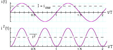
The power p converted in a resistor (ie the rate of conversion of electrical energy to heat) is
p(t) = iv = v2/R = i2R.
We use lower case p(t) because this is the expression for the instantaneous power at time t. Usually, we are interested in the mean power delivered, which is normally written P. P is the total energy converted in one cycle, divided by the period T of the cycle, so:
In the last line, we have used a standard trigonometrical identity that cos(2A) = 1 - 2 sin2A. Now the sinusoidal term averages to zero over any number of complete cycles, so the integral is simple and we obtain
This last set of equations are useful because they are exactly those normally used for a resistor in DC electricity. However, one must remember that P is the average power, and V = Vm/21/2 and I= Im/21/2. Looking at the integral above, and dividing by R, we see that I is equal to the square root of the mean value of i2, so I is called the root-mean-square or RMS value. Similarly, V = Vm/21/2 ~ 0.71*Vm is the RMS value of the voltage.
When talking of AC, RMS values are so commonly used that, unless otherwise stated, you may assume that RMS values are intended*. For instance, normal domestic AC in Australia is 240 Volts AC with frequency 50 Hz. The RMS voltage is 240 volts, so the peak value Vm= V.21/2 = 340 volts. So the active wire goes from +340 volts to -340 volts and back again 50 times per second. (This is the answer to the teaser question at the top of the page: rectification of the 240 V mains can give both + 340 Vdc and -340 Vdc.)
* An exception: manufacturers and sellers of HiFi equipment sometimes use peak values rather than RMS values, which makes the equipment seem more powerful than it is. Power in a resistor. In a resistor R, the peak power (achieved instantaneously 100 times per second for 50 Hz AC) is Vm2/R = im2*R. As discussed above, the voltage, current and so the power pass through zero volts 100 times per second, so the average power is less than this. The average is exactly as shown above: P = Vm2/2R = V2/R. Power in inductors and capacitors. In ideal inductors and capacitors, a sinusoidal current produces voltages that are respecively 90° ahead and behind the phase of the current. So if i = Imsin wt, the voltages across the inductor and capacitor are Vmcos wt and -Vmcos wt respectively. Now the integral of cos*sin over a whole number of cycles is zero. Consequently, ideal inductors and capacitors do not, on average, take power from the circuit.
When we connect components together, Kirchoff's laws apply at any instant. So the voltage v(t) across a resistor and capacitor in series is just
vseries(t) = vR(t) + vC(t)
however the addition is complicated because the two are not in phase. The next animation makes this clear: they add to give a new sinusoidal voltage, but the amplitude is less than VmR(t) + VmC(t). Similarly, the AC voltages (amplitude times √2) do not add up. This may seem confusing, so it's worth repeating:
vseries = vR + vC but Vseries < VR + VC.
This should be clear on the animation and the still graphic below: check that the voltages v(t) do add up, and then look at the magnitudes. The amplitudes and the RMS voltages V do not add up in a simple arithmetical way.
Here's where phasor diagrams are going to save us a lot of work. Play the animation again (click play), and look at the projections on the vertical axis. Because we have sinusoidal variation in time, the vertical component (magnitude times the sine of the angle it makes with the x axis) gives us v(t). But the y components of different vectors, and therefore phasors, add up simply: if
rtotal = r1 + r2, then ry total = ry1 + ry2.
So v(t), the sum of the y projections of the component phasors, is just the y projection of the sum of the component phasors. So we can represent the three sinusoidal voltages by their phasors. (While you're looking at it, check the phases. You'll see that the series voltage is behind the current in phase, but the relative phase is somewhere between 0 and 90°, the exact value depending on the size of VR and VC. We'll discuss phase below.)Now let's stop that animation and label the values, which we do in the still figure below. All of the variables (i, vR, vC, vseries) have the same frequency f and the same angular frequency ω, so their phasors rotate together, with the same relative phases. So we can 'freeze' it in time at any instant to do the analysis. The convention I use is that the x axis is the reference direction, and the reference is whatever is common in the circuit. In this series circuit, the current is common. (In a parallel circuit, the voltage is common, so I would make the voltage the horizontal axis.) Be careful to distinguish v and V in this figure!
(Careful readers will note that I'm taking a shortcut in these diagrams: the size of the arrows on the phasor diagrams are drawn the same as the amplitudes on the v(t) graphs. However I am just calling them VR, VC etc, rather than VmR, VmR etc. The reason is that the peak values (VmR etc) are rarely used in talking about AC: we use the RMS values, which are peak values times 0.71. Phasor diagrams in RMS have the same shape as those drawn using amplitudes, but everything is scaled by a factor of 0.71 = 1/√2.)The phasor diagram at right shows us a simple way to calculate the series voltage. The components are in series, so the current is the same in both. The voltage phasors (brown for resistor, blue for capacitor in the convention we've been using) add according to vector or phasor addition, to give the series voltage (the red arrow). By now you don't need to look at v(t), you can go straight from the circuit diagram to the phasor diagram, like this:
From Pythagoras' theorem:
V2mRC = V2mR + V2mC
If we divide this equation by two, and remembering that the RMS value V = Vm/√2, we also get:
Now this looks like Ohm's law again: V is proportional to I. Their ratio is the series impedance, Zseries and so for this series circuit,
Note the frequency dependence of the series impedance ZRC: at low frequencies, the impedance is very large, because the capacitive reactance 1/ωC is large (the capacitor is open circuit for DC). At high frequencies, the capacitive reactance goes to zero (the capacitor doesn't have time to charge up) so the series impedance goes to R. At the angular frequency ω = ωo = 1/RC, the capacitive reactance 1/ωC equals the resistance R. We shall show this characteristic frequency* on all graphs on this page.
* Let's check the units: it should be quick. First, a radian is the ratio of an arc to a radius, so it is a pure number. R is in ohms, and we can use Ohm's law (V = IR) and the definition of current (I = dQ/dt) to write ohm = volt/ampere = volt/(coulomb/second) = volt*second/coulomb. C (charge per unit voltage) is in farads (coulomb/volt), so RC has the units of (volt*second/coulomb)(coulomb/volt) = second. See, it was quick: it only took us 30 ohm.farads!
Remember how, for two resistors in series, you could just add the resistances: Rseries = R1 + R2 to get the resistance of the series combination. That simple result comes about because the two voltages are both in phase with the current, so their phasors are parallel. Because the phasors for reactances are 90° out of phase with the current, the series impedance of a resistor R and a reactance X are given by Pythagoras' law:
Zseries2 = R2 + X2 .
Ohm's law in AC. We can rearrange the equations above to obtain the current flowing in this circuit. Alternatively we can simply use the Ohm's Law analogy and say that I = Vsource/ZRC. Either way we get
where the current goes to zero at DC (capacitor is open circuit) and to V/R at high frequencies (no time to charge the capacitor).So far we have concentrated on the magnitude of the voltage and current. We now derive expressions for their relative phase, so let's look at the phasor diagram again.
From simple trigonometry, the angle by which the current leads the voltage is
However, we shall refer to the angle φ by which the voltage leads the current. The voltage is behind the current because the capacitor takes time to charge up, so φ is negative, ie
φ = -tan-1 (1/ωRC) = tan-1 (1/2πfRC).
At low frequencies, the impedance of the series RC circuit is dominated by the capacitor, so the voltage is 90° behind the current. At high frequencies, the impedance approaches R and the phase difference approaches zero. The frequency dependence of Z and φ are important in the applications of RC circuits. The voltage is mainly across the capacitor at low frequencies, and mainly across the resistor at high frequencies. Of course the two voltages must add up to give the voltage of the source, but they add up as vectors.
V2RC = V2R + V2C.
At the frequency ω = ωo = 1/RC, the phase φ = 45° and the voltage fractions are VR/VRC = VC/VRC = 1/2V1/2 = 0.71.
So, by chosing to look at the voltage across the resistor, you select mainly the high frequencies, across the capacitor, you select low frequencies. This brings us to one of the very important applications of RC circuits, and one which merits its own page: where we use sound files as examples of RC filtering.
Single phase is used in domestic applications for low power applications but it has some drawbacks. One is that it turns off 100 times per second (you don't notice that the fluorescent lights flicker at this speed because your eyes are too slow: even 25 pictures per second on the TV is fast enough to give the illusion of continuous motion.) The second is that it makes it awkward to produce rotating magnetic fields. For this reason, some high power (several kW) domestic devices may require three phase installation. Industrial applications use three phase extensively, and the three phase induction motor is a standard workhorse for high power applications. The three wires (not counting earth) carry three possible potential differences which are out of phase with each other by 120°, as shown in the animation below. Thus three stators give a smoothly rotating field.
If one puts a permanent magnet in such a set of stators, it becomes a synchronous three phase motor. The animation shows a squirrel cage, in which for simplicity only one of the many induced current loops is shown. With no mechanical load, it is turning virtually in phase with the rotating field. The rotor need not be a squirrel cage: in fact any conductor that will carry eddy currents will rotate, tending to follow the rotating field. This arrangement can give an induction motor capable of high efficiency, high power and high torques over a range of rotation rates.
A simple DC motor has a coil of wire that can rotate in a magnetic field. The current in the coil is supplied via two brushes that make moving contact with a split ring. The coil lies in a steady magnetic field. The forces exerted on the current-carrying wires create a torque on the coil.
The force F on a wire of length L carrying a current i in a magnetic field B is iLB times the sine of the angle between B and i, which would be 90° if the field were uniformly vertical. The direction of F comes from the right hand rule*, as shown here. The two forces shown here are equal and opposite, but they are displaced vertically, so they exert a torque. (The forces on the other two sides of the coil act along the same line and so exert no torque.)
* A number of different nmemonics are used to remember the direction of the force. Some use the right hand, some the left. For students who know vector multiplication, it is easy to use the Lorentz force directly: F = q vXB , whence F = i dLXB . That is the origin of the diagram shown here.
The coil can also be considered as a magnetic dipole, or a little electromagnet, as indicated by the arrow SN: curl the fingers of your right hand in the direction of the current, and your thumb is the North pole. In the sketch at right, the electromagnet formed by the coil of the rotor is represented as a permanent magnet, and the same torque (North attracts South) is seen to be that acting to align the central magnet.Note the effect of the brushes on the split ring. When the plane of the rotating coil reaches horizontal, the brushes will break contact (not much is lost, because this is the point of zero torque anyway – the forces act inwards). The angular momentum of the coil carries it past this break point and the current then flows in the opposite direction, which reverses the magnetic dipole. So, after passing the break point, the rotor continues to turn anticlockwise and starts to align in the opposite direction. In the following text, I shall largely use the 'torque on a magnet' picture, but be aware that the use of brushes or of AC current can cause the poles of the electromagnet in question to swap position when the current changes direction.
The torque generated over a cycle varies with the vertical separation of the two forces. It therefore depends on the sine of the angle between the axis of the coil and field. However, because of the split ring, it is always in the same sense. The animation below shows its variation in time, and you can stop it at any stage and check the direction by applying the right hand rule.
Some notes about AC and DC motors for high power applications
This site was originally written to help high school students and teachers in New South Wales, Australia, where a new syllabus concentrating on the history and applications of physics, at the expense of physics itself, has been introduced. The new syllabus, in one of the dot points, has this puzzling requirement: "explain that AC motors usually produce low power and relate this to their use in power tools".
AC motors are used for high power applications whenever it is possible. Three phase AC induction motors are widely used for high power applications, including heavy industry. However, such motors are unsuitable if multiphase is unavailable, or difficult to deliver. Electric trains are an example: it is easier to build power lines and pantographs if one only needs one active conductor, so this usually carries DC, and many train motors are DC. However, because of the disadvantages of DC for high power, more modern trains convert the DC into AC and then run three phase motors.Single phase induction motors have problems for applications combining high power and flexible load conditions. The problem lies in producing the rotating field. A capacitor could be used to put the current in one set of coils ahead, but high value, high voltage capacitors are expensive. Shaded poles are used instead, but the torque is small at some angles. If one cannot produce a smoothly rotating field, and if the load 'slips' well behind the field, then the torque falls or even reverses.
Power tools and some appliances use brushed AC motors. Brushes introduce losses (plus arcing and ozone production). The stator polarities are reversed 100 times a second. Even if the core material is chosen to minimise hysteresis losses ('iron losses'), this contributes to inefficiency, and to the possibility of overheating. These motors may be called 'universal' because they can operate on DC. This solution is cheap, but crude and inefficient. For relatively low power applications like power tools, the inefficiency is usually not economically important.
If only single phase AC is available, one may rectify the AC and use a DC motor. High current rectifiers used to be expensive, but are becoming less expensive and more widely used. If you are confident you understand the principles, it's time to go to How real electric motors work by John Storey. Or else continue here to find out about loudspeakers and transformers.
A set of coils can be used to create a magnetic field that translates, rather than rotates. The pair of coils in the animation below are pulsed on, from left to right, so the region of magnetic field moves from left to right. A permanent or electromagnet will tend to follow the field. So would a simple slab of conducting material, because the eddy currents induced in it (not shown) comprise an electromagnet. Alternatively, we could say that, from Faraday's law, an emf in the metal slab is always induced so as to oppose any change in magnetic flux, and the forces on the currents driven by this emf keep the flux in the slab nearly constant. (Eddy currents not shown in this animation.)
Alternatively, we could have sets of powered coils in the moving part, and induce eddy currents in the rail. Either case gives us a linear motor, which would be useful for say maglev trains. (In the animation, the geometry is, as usual on this site, highly idealised, and only one eddy current is shown.)

.gif)
2.gif)
 The power p converted in a resistor (ie the rate of conversion of electrical energy to heat) is
.gif)
.gif)
.gif)
.gif)