
Capacitors and charging
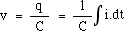
The voltage on a capacitor depends on the amount of charge you store on its plates. The current flowing onto the positive capacitor plate (equal to that flowing off the negative plate) is by definition the rate at which charge is being stored. So the charge Q on the capacitor equals the integral of the current with respect to time. From the definition of the capacitance,- vC = q/C, so
Once again we have a sinusoidal current i = Im . sin (ωt), so integration gives
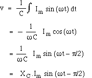
Now we define the capacitive reactance XC as the ratio of the magnitude of the voltage to magnitude of the current in a capacitor. From the equation above, we see that XC = 1/ωC. Now we can rewrite the equation above to make it look like Ohm's law. The voltage is proportional to the current, and the peak voltage and current are related by
- Vm = XC.Im.
Recall that reactance is the name for the ratio of voltage to current when they differ in phase by 90°. (If they are in phase, the ratio is called resistance.) Another difference between reactance and resistance is that the reactance is frequency dependent. From the algebra above, we see that the capacitive reactance XCdecreases with frequency . This is shown in the next animation: when the frequency is halved but the current amplitude kept constant, the capacitor has twice as long to charge up, so it generates twice the potential difference. The blue shading shows q, the integral under the current curve (light for positive, dark for negative). The second and fourth curves show VC = q/C . See how the lower frequency leads to a larger charge (bigger shaded area before changing sign) and therefore a larger VC.
Thus for a capacitor, the ratio of voltage to current decreases with frequency. We shall see later how this can be used for filtering different frequencies.