Web hosting

Thursday, December 30, 2010

DC motors

DC motors

A simple DC motor has a coil of wire that can rotate in a magnetic field. The current in the coil is supplied via two brushes that make moving contact with a split ring. The coil lies in a steady magnetic field. The forces exerted on the current-carrying wires create a torque on the coil.

schematic of motor
The force F on a wire of length L carrying a current i in a magnetic field B is iLB times the sine of the angle between B and i, which would be 90° if the field were uniformly vertical. The direction of F comes from the right hand rule*, as shown here. The two forces shown here are equal and opposite, but they are displaced vertically, so they exert a torque. (The forces on the other two sides of the coil act along the same line and so exert no torque.)
    * A number of different nmemonics are used to remember the direction of the force. Some use the right hand, some the left. For students who know vector multiplication, it is easy to use the Lorentz force directly:  F  =  q v X B ,  whence F  =  i dL X B . That is the origin of the diagram shown here.
The coil can also be considered as a magnetic dipole, or a little electromagnet, as indicated by the arrow SN: curl the fingers of your right hand in the direction of the current, and your thumb is the North pole. In the sketch at right, the electromagnet formed by the coil of the rotor is represented as a permanent magnet, and the same torque (North attracts South) is seen to be that acting to align the central magnet.Note the effect of the brushes on the split ring. When the plane of the rotating coil reaches horizontal, the brushes will break contact (not much is lost, because this is the point of zero torque anyway – the forces act inwards). The angular momentum of the coil carries it past this break point and the current then flows in the opposite direction, which reverses the magnetic dipole. So, after passing the break point, the rotor continues to turn anticlockwise and starts to align in the opposite direction. In the following text, I shall largely use the 'torque on a magnet' picture, but be aware that the use of brushes or of AC current can cause the poles of the electromagnet in question to swap position when the current changes direction.
The torque generated over a cycle varies with the vertical separation of the two forces. It therefore depends on the sine of the angle between the axis of the coil and field. However, because of the split ring, it is always in the same sense. The animation below shows its variation in time, and you can stop it at any stage and check the direction by applying the right hand rule.


Thursday, November 25, 2010

Some notes about AC and DC motors for high power applications

Some notes about AC and DC motors for high power applications

    This site was originally written to help high school students and teachers in New South Wales, Australia, where a new syllabus concentrating on the history and applications of physics, at the expense of physics itself, has been introduced. The new syllabus, in one of the dot points, has this puzzling requirement: "explain that AC motors usually produce low power and relate this to their use in power tools".
AC motors are used for high power applications whenever it is possible. Three phase AC induction motors are widely used for high power applications, including heavy industry. However, such motors are unsuitable if multiphase is unavailable, or difficult to deliver. Electric trains are an example: it is easier to build power lines and pantographs if one only needs one active conductor, so this usually carries DC, and many train motors are DC. However, because of the disadvantages of DC for high power, more modern trains convert the DC into AC and then run three phase motors.Single phase induction motors have problems for applications combining high power and flexible load conditions. The problem lies in producing the rotating field. A capacitor could be used to put the current in one set of coils ahead, but high value, high voltage capacitors are expensive. Shaded poles are used instead, but the torque is small at some angles. If one cannot produce a smoothly rotating field, and if the load 'slips' well behind the field, then the torque falls or even reverses.
Power tools and some appliances use brushed AC motors. Brushes introduce losses (plus arcing and ozone production). The stator polarities are reversed 100 times a second. Even if the core material is chosen to minimise hysteresis losses ('iron losses'), this contributes to inefficiency, and to the possibility of overheating. These motors may be called 'universal' because they can operate on DC. This solution is cheap, but crude and inefficient. For relatively low power applications like power tools, the inefficiency is usually not economically important.
If only single phase AC is available, one may rectify the AC and use a DC motor. High current rectifiers used to be expensive, but are becoming less expensive and more widely used. If you are confident you understand the principles, it's time to go to How real electric motors work by John Storey. Or else continue here to find out about loudspeakers and transformers.

Tuesday, November 23, 2010

Linear motors

Linear motors

A set of coils can be used to create a magnetic field that translates, rather than rotates. The pair of coils in the animation below are pulsed on, from left to right, so the region of magnetic field moves from left to right. A permanent or electromagnet will tend to follow the field. So would a simple slab of conducting material, because the eddy currents induced in it (not shown) comprise an electromagnet. Alternatively, we could say that, from Faraday's law, an emf in the metal slab is always induced so as to oppose any change in magnetic flux, and the forces on the currents driven by this emf keep the flux in the slab nearly constant. (Eddy currents not shown in this animation.)


Alternatively, we could have sets of powered coils in the moving part, and induce eddy currents in the rail. Either case gives us a linear motor, which would be useful for say maglev trains. (In the animation, the geometry is, as usual on this site, highly idealised, and only one eddy current is shown.)


Build a simple motor

Build a simple motor

To build this simple but strange motor, you need two fairly strong magnets (rare earth magnets about 10 mm diameter would be fine, as would larger bar magnets), some stiff copper wire (at least 50 cm), two wires with crocodile clips on either end, a six volt lantern battery, two soft drink cans, two blocks of wood, some sticky tape and a sharp nail.


Make the coil out of stiff copper wire, so it doesn't need any external support. Wind 5 to 20 turns in a circle about 20 mm in diameter, and have the two ends point radially outwards in opposite directions. These ends will be both the axle and the contacts. If the wire has lacquer or plastic insulation, strip it off at the ends
The supports for the axle can be made of aluminium, so that they make electrical contact. For example poke holes in a soft drink cans with a nail as shown. Position the two magnets, north to south, so that the magnetic field passes through the coil at right angles to the axles. Tape or glue the magnets onto the wooden blocks (not shown in the diagram) to keep them at the right height, then move the blocks to put them in position, rather close to the coil. Rotate the coil initially so that the magnetic flux through the coil is zero, as shown in the diagram.Now get a battery, and two wires with crocodile clips. Connect the two terminals of the battery to the two metal supports for the coil and it should turn.
Note that this motor has at least one 'dead spot': It often stops at the position where there is no torque on the coil. Don't leave it on too long: it will flatten the battery quickly.The optimum number of turns in the coil depends on the internal resistance of the battery, the quality of the support contacts and the type of wire, so you should experiment with different values.
As mentioned above, this is also a generator, but it is a very inefficient one. To make a larger emf, use more turns (you may need to use finer wire and a frame upon which to wind it.) You could use eg an electric drill to turn it quickly, as shown in the sketch above. Use an oscilloscope to look at the emf generated. Is it AC or DC?
This motor has no split ring, so why does it work on DC? Simply put, if it were exactly symmetrical, it wouldn't work. However, if the current is slightly less in one half cycle than the other, then the average torque will not be zero and, because it spins reasonably rapidly, the angular momentum acquired during the half cycle with greater current carries it through the half cycle when the torque is in the opposite direction. At least two effects can cause an asymmetry. Even if the wires are perfectly stripped and the wires clean, the contact resistance is unlikely to be exactly equal, even at rest. Also, the rotation itself causes the contact to be intermittent so, if there are longer bounces during one phase, this asymmetry is sufficient. In principle, you could partially strip the wires in such a way that the current would be zero in one half cycle.
title


An alternative relisation of the simple motor, by James Taylor.
An even simpler motor (one that is also much simpler to understand!) is the homopolar motor.

Power in resistive and reactive AC circuits

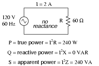
Consider a circuit for a single-phase AC power system, where a 120 volt, 60 Hz AC voltage source is delivering power to a resistive load: (Figure below)

Ac source drives a purely resistive load.


In this example, the current to the load would be 2 amps, RMS. The power dissipated at the load would be 240 watts. Because this load is purely resistive (no reactance), the current is in phase with the voltage, and calculations look similar to that in an equivalent DC circuit. If we were to plot the voltage, current, and power waveforms for this circuit, it would look like Figure below.

Current is in phase with voltage in a resistive circuit.
Note that the waveform for power is always positive, never negative for this resistive circuit. This means that power is always being dissipated by the resistive load, and never returned to the source as it is with reactive loads. If the source were a mechanical generator, it would take 240 watts worth of mechanical energy (about 1/3 horsepower) to turn the shaft.
Also note that the waveform for power is not at the same frequency as the voltage or current! Rather, its frequency is double that of either the voltage or current waveforms. This different frequency prohibits our expression of power in an AC circuit using the same complex (rectangular or polar) notation as used for voltage, current, and impedance, because this form of mathematical symbolism implies unchanging phase relationships. When frequencies are not the same, phase relationships constantly change.
As strange as it may seem, the best way to proceed with AC power calculations is to use scalar notation, and to handle any relevant phase relationships with trigonometry.
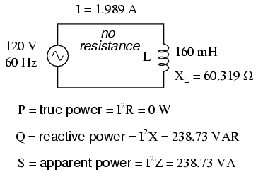
For comparison, let's consider a simple AC circuit with a purely reactive load in Figure below.

AC circuit with a purely reactive (inductive) load.


Power is not dissipated in a purely reactive load. Though it is alternately absorbed from and returned to the source.
Note that the power alternates equally between cycles of positive and negative. (Figure above) This means that power is being alternately absorbed from and returned to the source. If the source were a mechanical generator, it would take (practically) no net mechanical energy to turn the shaft, because no power would be used by the load. The generator shaft would be easy to spin, and the inductor would not become warm as a resistor would.
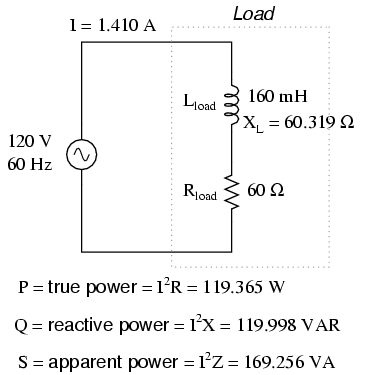
Now, let's consider an AC circuit with a load consisting of both inductance and resistance in Figure below.

AC circuit with both reactance and resistance.


At a frequency of 60 Hz, the 160 millihenrys of inductance gives us 60.319 Ω of inductive reactance. This reactance combines with the 60 Ω of resistance to form a total load impedance of 60 + j60.319 Ω, or 85.078 Ω ∠ 45.152o. If we're not concerned with phase angles (which we're not at this point), we may calculate current in the circuit by taking the polar magnitude of the voltage source (120 volts) and dividing it by the polar magnitude of the impedance (85.078 Ω). With a power supply voltage of 120 volts RMS, our load current is 1.410 amps. This is the figure an RMS ammeter would indicate if connected in series with the resistor and inductor.
We already know that reactive components dissipate zero power, as they equally absorb power from, and return power to, the rest of the circuit. Therefore, any inductive reactance in this load will likewise dissipate zero power. The only thing left to dissipate power here is the resistive portion of the load impedance. If we look at the waveform plot of voltage, current, and total power for this circuit, we see how this combination works in Figure below.

A combined resistive/reactive circuit dissipates more power than it returns to the source. The reactance dissipates no power; though, the resistor does.
As with any reactive circuit, the power alternates between positive and negative instantaneous values over time. In a purely reactive circuit that alternation between positive and negative power is equally divided, resulting in a net power dissipation of zero. However, in circuits with mixed resistance and reactance like this one, the power waveform will still alternate between positive and negative, but the amount of positive power will exceed the amount of negative power. In other words, the combined inductive/resistive load will consume more power than it returns back to the source.
Looking at the waveform plot for power, it should be evident that the wave spends more time on the positive side of the center line than on the negative, indicating that there is more power absorbed by the load than there is returned to the circuit. What little returning of power that occurs is due to the reactance; the imbalance of positive versus negative power is due to the resistance as it dissipates energy outside of the circuit (usually in the form of heat). If the source were a mechanical generator, the amount of mechanical energy needed to turn the shaft would be the amount of power averaged between the positive and negative power cycles.

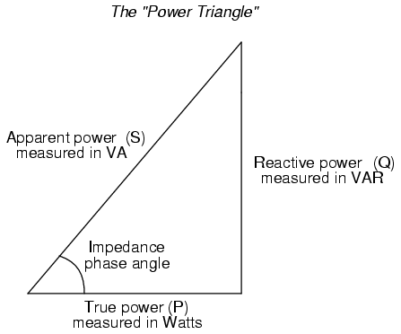
Mathematically representing power in an AC circuit is a challenge, because the power wave isn't at the same frequency as voltage or current. Furthermore, the phase angle for power means something quite different from the phase angle for either voltage or current. Whereas the angle for voltage or current represents a relative shift in timing between two waves, the phase angle for power represents a ratio between power dissipated and power returned. Because of this way in which AC power differs from AC voltage or current, it is actually easier to arrive at figures for power by calculating with scalar quantities of voltage, current, resistance, and reactance than it is to try to derive it from vector, or complex quantities of voltage, current, and impedance that we've worked with so far.
  • REVIEW:
  • In a purely resistive circuit, all circuit power is dissipated by the resistor(s). Voltage and current are in phase with each other.
  • In a purely reactive circuit, no circuit power is dissipated by the load(s). Rather, power is alternately absorbed from and returned to the AC source. Voltage and current are 90o out of phase with each other.
  • In a circuit consisting of resistance and reactance mixed, there will be more power dissipated by the load(s) than returned, but some power will definitely be dissipated and some will merely be absorbed and returned. Voltage and current in such a circuit will be out of phase by a value somewhere between 0o and 90o.

AC motors

AC motors

With AC currents, we can reverse field directions without having to use brushes. This is good news, because we can avoid the arcing, the ozone production and the ohmic loss of energy that brushes can entail. Further, because brushes make contact between moving surfaces, they wear out.The first thing to do in an AC motor is to create a rotating field. 'Ordinary' AC from a 2 or 3 pin socket is single phase AC--it has a single sinusoidal potential difference generated between only two wires--the active and neutral. (Note that the Earth wire doesn't carry a current except in the event of electrical faults.) With single phase AC, one can produce a rotating field by generating two currents that are out of phase using for example a capacitor. In the example shown, the two currents are 90° out of phase, so the vertical component of the magnetic field is sinusoidal, while the horizontal is cosusoidal, as shown. This gives a field rotating counterclockwise.
(* I've been asked to explain this: from simple AC theory, neither coils nor capacitors have the voltage in phase with the current. In a capacitor, the voltage is a maximum when the charge has finished flowing onto the capacitor, and is about to start flowing off. Thus the voltage is behind the current. In a purely inductive coil, the voltage drop is greatest when the current is changing most rapidly, which is also when the current is zero. The voltage (drop) is ahead of the current. In motor coils, the phase angle is rather less than 90¡, because electrical energy is being converted to mechanical energy.)


In this animation, the graphs show the variation in time of the currents in the vertical and horizontal coils. The plot of the field components Bx and By shows that the vector sum of these two fields is a rotating field. The main picture shows the rotating field. It also shows the polarity of the magnets: as above, blue represents a North pole and red a South pole.
If we put a permanent magnet in this area of rotating field, or if we put in a coil whose current always runs in the same direction, then this becomes a synchronous motor. Under a wide range of conditions, the motor will turn at the speed of the magnetic field. If we have a lot of stators, instead of just the two pairs shown here, then we could consider it as a stepper motor: each pulse moves the rotor on to the next pair of actuated poles. Please remember my warning about the idealised geometry: real stepper motors have dozens of poles and quite complicated geometries!


Bandwidth and Q factor

Bandwidth and Q factor

At resonance, the voltages across the capacitor and the pure inductance cancel out, so the series impedance takes its minimum value: Zo = R. Thus, if we keep the voltage constant, the current is a maximum at resonance. The current goes to zero at low frequency, because XC becomes infinite (the capacitor is open circuit for DC). The current also goes to zero at high frequency because XL increases with ω (the inductor opposes rapid changes in the current). The graph shows I(ω) for circuit with a large resistor (lower curve) and for one with a small resistor (upper curve). A circuit with low R, for a given L and C, has a sharp resonance. Increasing the resistance makes the resonance less sharp. The former circuit is more selective: it produces high currents only for a narrow bandwidth, ie a small range of ω or f. The circuit with higher R responds to a wider range of frequencies and so has a larger bandwidth. The bandwidth Δω (indicated by the horiztontal bars on the curves) is defined as the difference between the two frequencies ω+ and ω- at which the circuit converts power at half the maximum rate.Now the electrical power converted to heat in this circuit is I2R, so the maximum power is converted at resonance, ω = ωo. The circuit converts power at half this rate when the current is Io/√2. The Q value is defined as the ratio
    Q  =  ωo/Δω.
bandwidth pic

Resonance

Resonance

Note that the expression for the series impedance goes to infinity at high frequency because of the presence of the inductor, which produces a large emf if the current varies rapidly. Similarly it is large at very low frequencies because of the capacitor, which has a long time in each half cycle in which to charge up. As we saw in the plot of Zseriesω above, there is a minimum value of the series impedance, when the voltages across capacitor and inductor are equal and opposite, ie vL(t) = - vC(t) so VL(t) = VC, so
    ωL = 1/ωC        so the frequency at which this occurs isAC equations
where ωo and fo are the angular and cyclic frequencies of resonance, respectively. At resonance, series impedance is a minimum, so the voltage for a given current is a minimum (or the current for a given voltage is a maximum).
This phenomenon gives the answer to our teaser question at the beginning. In an RLC series circuit in which the inductor has relatively low internal resistance r, it is possible to have a large voltage across the the inductor, an almost equally large voltage across capacitor but, as the two are nearly 180° degrees out of phase, their voltages almost cancel, giving a total series voltage that is quite small. This is one way to produce a large voltage oscillation with only a small voltage source. In the circuit diagram at right, the coil corresponds to both the inducance L and the resistance r, which is why they are drawn inside a box representing the physical component, the coil. Why are they in series? Because the current flows through the coil and thus passes through both the inductance of the coil and its resistance.You get a big voltage in the circuit for only a small voltage input from the power source. You are not, of course, getting something for nothing. The energy stored in the large oscillations is gradually supplied by the AC source when you turn on, and it is then exchanged between capacitor and inductor in each cycle. For more details about this phenomenon, and a discussion of the energies involved.
resonance pic

RL Series combinations

RL Series combinations

In an RL series circuit, the voltage across the inductor is aheadof the current by 90°, and the inductive reactance, as we saw before, is X= ωL. The resulting v(t) plots and phasor diagram look like this.
    RL series circuit
It is straightforward to use Pythagoras' law to obtain the series impedance and trigonometry to obtain the phase. We shall not, however, spend much time on RL circuits, for three reasons. First, it makes a good exercise for you to do it yourself. Second, RL circuits are used much less than RC circuits. This is because inductors are always* too big, too expensive and the wrong value, a proposition you can check by looking at an electronics catalogue. If you can use a circuit involving any number of Rs, Cs, transistors, integrated circuits etc to replace an inductor, one usually does. The third reason why we don't look closely at RL circuits on this site is that you can simply look at RLC circuits (below) and omit the phasors and terms for the capacitance.* Exceptions occur at high frequencies (~GHz) where only small value Ls are required to get substantial ωL. In such circuits, one makes an inductor by twisting copper wire around a pencil and adjusts its value by squeezing it with the fingers.

Impedance of components

Impedance of components

Let's recap what we now know about voltage and curent in linear components. The impedance is the general term for the ratio of voltage to current. Resistance is the special case of impedance when φ = 0, reactance the special case when φ = ± 90°. The table below summarises the impedance of the different components. It is easy to remember that the voltage on the capacitor is behind the current, because the charge doesn't build up until after the current has been flowing for a while.
    AC equations
The same information is given graphically below. It is easy to remember the frequency dependence by thinking of the DC (zero frequency) behaviour: at DC, an inductance is a short circuit (a piece of wire) so its impedance is zero. At DC, a capacitor is an open circuit, as its circuit diagram shows, so its impedance goes to infinity.
    AC equations

Inductors and the Farady emf

Inductors and the Farady emf

An inductor is usually a coil of wire. In an ideal inductor, the resistance of this wire is negligibile, as is its capacitance. The voltage that appears across an inductor is due to its own magnetic field and Faraday's law of electromagnetic induction. The current i(t) in the coil sets up a magnetic field, whose magnetic flux φB is proportional to the field strength, which is proportional to the current flowing. (Do not confuse the phase φ with the flux φB.) So we define the (self) inductance of the coil thus:
    φB(t) = L.i(t)
Faraday's law gives the emf EL = - dφB/dt. Now this emf is a voltage rise, so for the voltage drop vL across the inductor, we have:
    AC equations
Again we define the inductive reactance XL as the ratio of the magnitudes of the voltage and current, and from the equation above we see that XL = ωL. Again we note the analogy to Ohm's law: the voltage is proportional to the current, and the peak voltage and currents are related by

    Vm = XL.Im.
Remembering that the derivative is the local slope of the curve (the purple line), we can see in the next animation why voltage and current are out of phase in an inductor.

Again, there is a difference in phase: the derivative of the sinusoidal current is a cos function: it has its maximum (largest voltage across the inductor) when the current is changing most rapidly, which is when the current is intantaneously zero. The animation should make this clear. The voltage across the ideal inductor is 90° ahead of the current, (ie it reaches its peak one quarter cycle before the current does). Note how this is represented on the phasor diagram.
Again we note that the reactance is frequency dependent XL = ωL. This is shown in the next animation: when the frequency is halved but the current amplitude kept constant, the current is varying only half as quickly, so its derivative is half as great, as is the Faraday emf. For an inductor, the ratio of voltage to current increases with frequency, as the next animation shows.


Capacitors and charging

Capacitors and charging

The voltage on a capacitor depends on the amount of charge you store on its plates. The current flowing onto the positive capacitor plate (equal to that flowing off the negative plate) is by definition the rate at which charge is being stored. So the charge Q on the capacitor equals the integral of the current with respect to time. From the definition of the capacitance,
    vC = q/C, soAC equations
Now remembering that the integral is the area under the curve (shaded blue), we can see in the next animation why the current and voltage are out of phase.
Once again we have a sinusoidal current i = Im . sin (ωt), so integration gives

    AC equations
(The constant of integration has been set to zero so that the average charge on the capacitor is 0).
Now we define the capacitive reactance XC as the ratio of the magnitude of the voltage to magnitude of the current in a capacitor. From the equation above, we see that XC = 1/ωC. Now we can rewrite the equation above to make it look like Ohm's law. The voltage is proportional to the current, and the peak voltage and current are related by

    Vm = XC.Im.
Note the two important differences. First, there is a difference in phase: the integral of the sinusoidal current is a negative cos function: it reaches its maximum (the capacitor has maximum charge) when the current has just finished flowing forwards and is about to start flowing backwards. Run the animation again to make this clear. Looking at the relative phase, the voltage across the capacitor is 90°, or one quarter cycle, behind the current. We can see also see how the φ = 90° phase difference affects the phasor diagrams at right. Again, the vertical component of a phasor arrow represents the instantaneous value of its quanitity. The phasors are rotating counter clockwise (the positive direction) so the phasor representing VC is 90° behind the current (90° clockwise from it).
Recall that reactance is the name for the ratio of voltage to current when they differ in phase by 90°. (If they are in phase, the ratio is called resistance.) Another difference between reactance and resistance is that the reactance is frequency dependent. From the algebra above, we see that the capacitive reactance XCdecreases with frequency . This is shown in the next animation: when the frequency is halved but the current amplitude kept constant, the capacitor has twice as long to charge up, so it generates twice the potential difference. The blue shading shows q, the integral under the current curve (light for positive, dark for negative). The second and fourth curves show VC = q/C . See how the lower frequency leads to a larger charge (bigger shaded area before changing sign) and therefore a larger VC.

Thus for a capacitor, the ratio of voltage to current decreases with frequency. We shall see later how this can be used for filtering different frequencies.

Resistors and Ohm's law in AC circuits

Resistors and Ohm's law in AC circuits

The voltage v across a resistor is proportional to the current i travelling through it.
Further, this is true at all times: v = Ri. So, if the current in a resistor is
    i = Im . sin (ωt) ,           we write: v = R.i = R.Im sin (ωt) v = Vm. sin (ωt)            where Vm = R.Im
So for a resistor, the peak value of voltage is R times the peak value of current. Further, they are in phase: when the current is a maximum, the voltage is also a maximum. (Mathematically, φ = 0.) The first animation shows the voltage and current in a resistor as a function of time.

The rotating lines in the right hand part of the animation are a very simple case of a phasor diagram (named, I suppose, because it is a vector representation of phase). With respect to the x and y axes, radial vectors or phasors representing the current and the voltage across the resistance rotate with angular velocity ω. The lengths of these phasors represent the peak current Im and voltage Vm. The y components are Im sin (ωt) = i(t) and voltage Vm sin (ωt)= v(t). You can compare i(t) and v(t) in the animation with the vertical components of the phasors. The animation and phasor diagram here are simple, but they will become more useful when we consider components with different phases and with frequency dependent behaviour.

Three phase AC


Three phase AC

Single phase AC has the advantage that it only requires 2 wires. Its disadvantage is seen in the graph at the top of this page: twice every cycle V goes to zero. If you connect a phototransistor circuit to an oscilloscope, you will see that fluorescent lights turn off 100 times per second (or 120, if you are on 60 Hz supply). What if you need a more even supply of electricity? One can store energy in capacitors, of course, but with high power circuits this would require big, expensive capacitors. What to do?An AC generator may have more than one coil. If it has three coils, mounted at relative angles of 120°, then it will produce three sinusoidal emfs with relative phases of 120°, as shown in the upper figure at right. The power delivered to a resistive load by each of these is proportional to V2. The sum of the three V2 terms is a constant. We saw above that the average of V2 is half the peak value, so this constant is 1.5 times the peak amplitude for any one circuit, as is shown in the lower figure at right.
Do you need four wires? In principle, no. The sum of the three V terms is zero so, provided that the loads on each phase are identical, the currents drawn from the three lines add to zero. In practice, the current in the neutral wire is usually not quite zero. Further, it should be the same guage as the other wires because, if one of the loads were to fail and form an open circuit, the neutral would carry a current similar to that in the remaining two loads.
plot of V, V^2 for three phase
The voltage (top) and square of the voltage (bottom) in the three active lines of 3 phase supply.

Transformers

Transformers

The photograph shows a transformer designed for demonstration purposes: the primary and secondary coils are clearly separated, and may be removed and replaced by lifting the top section of the core. For our purposes, note that the coil on the left has fewer coils than that at right (the insets show close-ups).

diagrammatic of transformer
photo of transformer
The sketch and circuit show a step-up transformer. To make a step-down transformer, one only has to put the source on the right and the load on the left. (Important safety note: for a real transformer, you could only 'plug it in backwards' only after verifying that the voltage rating were appropriate.) So, how does a transformer work?The core (shaded) has high magnetic permeability, ie a material that forms a magnetic field much more easily than free space does, due to the orientation of atomic dipoles. (In the photograph, the core is laminated soft iron.) The result is that the field is concentrated inside the core, and almost no field lines leave the core. If follows that the magnetic fluxes φ through the primary and secondary are approximately equal, as shown. From Faraday's law, the emf in each turn, whether in the primary or secondary coil, is −dφ/dt. If we neglect resistance and other losses in the transformer, the terminal voltage equals the emf. For the Np turns of the primary, this gives
    Vp = − Np.dφ/dt .
For the Ns turns of the secondary, this gives
    Vs = − Ns.φ/dt
Dividing these equations gives the transformer equation
    Vs/Vp = Ns/Np = r.
where r is the turns ratio. What about the current? If we neglect losses in the transformer (see the section below on efficiency), and if we assume that the voltage and current have similar phase relationships in the primary and secondary, then from conservation of energy we may write, in steady state:
    Power in = power out,      soVpIp = VsIs,      whence Is/Ip = Np/Ns = 1/r.
So you don't get something for nothing: if you increase the voltage, you decrease the current by (at least) the same factor. Note that, in the photograph, the coil with more turns has thinner wire, because it is designed to carry less current than that with fewer turns.In some cases, decreasing the current is the aim of the exercise. In power transmission lines, for example, the power lost in heating the wires due to their non-zero resistance is proportional to the square of the current. So it saves a lot of energy to transmit the electrical power from power station to city at very high voltages so that the currents are only modest.
Finally, and again assuming that the transformer is ideal, let's ask what the resistor in the secondary circuit 'looks like' to the primary circuit. In the primary circuit:
    Vp = Vs/r       and       Ip = Is.r      soVp/Ip = Vs/r2Is = R/r2.
R/r2 is called the reflected resistance. Provided that the frequency is not too high, and provided that there is a load resistance (conditions usually met in practical transformers), the inductive reactance of the primary is much smaller than this reflected resistance, so the primary circuit behaves as though the source were driving a resistor of value R/r2.

Efficiency of transformers

In practice, real transformers are less than 100% efficient.
  • First, there are resistive losses in the coils (losing power I2.r). For a given material, the resistance of the coils can be reduced by making their cross section large. The resistivity can also be made low by using high purity copper. (See Drift velocity and Ohm's law)
  • Second, there are some eddy current losses in the core. These can be reduced by laminating the core. Laminations reduce the area of circuits in the core, and so reduce the Faraday emf, and so the current flowing in the core, and so the energy thus lost.
  • Third, there are hysteresis losses in the core. The magentisation and demagnetisation curves for magnetic materials are often a little different (hysteresis or history depedence) and this means that the energy required to magnetise the core (while the current is increasing) is not entirely recovered during demagnetisation. The difference in energy is lost as heat in the core.
  • Finally, the geometric design as well as the material of the core may be optimised to ensure that the magnetic flux in each coil of the secondary is nearly the same as that in each coil of the primary.

More about transformers: AC vs DC generators

Transformers only work on AC, which is one of the great advantages of AC. Transformers allow 240V to be stepped down to convenient levels for digital electronics (only a few volts) or for other low power applications (typically 12V). Transformers step the voltage up for transmission, as mentioned above, and down for safe distribution. Without transformers, the waste of electric power in distribution networks, already high, would be enormous. It is possible to convert voltages in DC, but more complicated than with AC. Further, such conversions are often inefficient and/or expensive. AC has the further advantage that it can be used on AC motors, which are usually preferable to DC motors for high power applications.

Loudspeakers

Loudspeakers

A loudspeaker is a linear motor with a small range. It has a single moving coil that is permanently but flexibly wired to the voltage source, so there are no brushes.

speaker diagrammatic
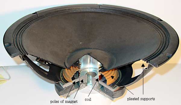
The coil moves in the field of a permanent magnet, which is usually shaped to produce maximum force on the coil. The moving coil has no core, so its mass is small and it may be accelerated quickly, allowing for high frequency motion. In a loudspeaker, the coil is attached to a light weight paper cone, which is supported at the inner and outer edges by circular, pleated paper 'springs'. In the photograph below, the speaker is beyond the normal upward limit of its travel, so the coil is visible above the magnet poles.For low frequency, large wavelength sound, one needs large cones. The speaker shown below is 380 mm diameter. Speakers designed for low frequencies are called woofers. They have large mass and are therefore difficult to accelerate rapidly for high frequency sounds. In the photograph below, a section has been cut away to show the internal components.
Tweeters - loudspeakers designed for high frequencies - may be just speakers of similar design, but with small, low mass cones and coils. Alternatively, they may use piezoelectric crystals to move the cone.

speaker photo

Speakers are seen to be linear motors with a modest range - perhaps tens of mm. Similar linear motors, although of course without the paper cone, are often used to move the reading and writing head radially on a disc drive.

Loudspeakers as microphones

In the picture above, you can see that a cardboard diaphragm (the loudspeaker cone) is connected to a coil of wire in a magnetic field. If a soundwave moves the diaphragm, the coil will move in the field, generating a voltage. This is the principle of a dynamic microphone – though in most microphones, the diaphragm is rather smaller than the cone of a loudspeaker. So, a loudspeaker should work as a microphone. This is a nice project: all you need is a loudspeaker and two wires to connect it to the input of an oscilloscope or the microphone input of your computer. Two questions: what do you think the mass of the cone and coil will do to the frequency response? What about the wavelength of sounds your use?

Induction motors

Induction motors

Now, since we have a time varying magnetic field, we can use the induced emf in a coil – or even just the eddy currents in a conductor – to make the rotor a magnet. That's right, once you have a rotating magnetic field, you can just put in a conductor and it turns. This gives several of the advantages of induction motors: no brushes or commutator means easier manufacture, no wear, no sparks, no ozone production and none of the energy loss associated with them. Below left is a schematic of an induction motor. (For photos of real induction motors and more details, see Induction motors.)

The animation at right represents a squirrel cage motor. The squirrel cage has (in this simplified geometry, anyhow!) two circular conductors joined by several straight bars. Any two bars and the arcs that join them form a coil – as indicated by the blue dashes in the animation. (Only two of the many possible circuits have been shown, for simplicity.)
This schematic suggests why they might be called squirrel cage motors. The reality is different: for photos and more details, see Induction motors. The problem with the induction and squirrel cage motors shown in this animation is that capacitors of high value and high voltage rating are expensive. One solution is the 'shaded pole' motor, but its rotating field has some directions where the torque is small, and it has a tendency to run backwards under some conditions. The neatest way to avoid this is to use multiple phase motors.

An alternator

An alternator

If we want AC, we don't need recification, so we don't need split rings. (This is good news, because the split rings cause sparks, ozone, radio interference and extra wear. If you want DC, it is often better to use an alternator and rectify with diodes.)In the next animation, the two brushes contact two continuous rings, so the two external terminals are always connected to the same ends of the coil. The result is the unrectified, sinusoidal emf given by NBAω sin ωt, which is shown in the next animation.

 
This is an AC generator. The advantages of AC and DC generator are compared in a section below. We saw above that a DC motor is also a DC generator. Similarly, an alternator is also an AC motor. However, it is a rather inflexible one.

Back emf

Now, as the first two animations show, DC motors and generators may be the same thing. For example, the motors of trains become generators when the train is slowing down: they convert kinetic energy into electrical energy and put power back into the grid. Recently, a few manufacturers have begun making motor cars rationally. In such cars, the electric motors used to drive the car are also used to charge the batteries when the car is stopped - it is called regenerative braking.So here is an interesting corollary. Every motor is a generator. This is true, in a sense, even when it functions as a motor. The emf that a motor generates is called the back emf. The back emf increases with the speed, because of Faraday's law. So, if the motor has no load, it turns very quickly and speeds up until the back emf, plus the voltage drop due to losses, equal the supply voltage. The back emf can be thought of as a 'regulator': it stops the motor turning infinitely quickly (thereby saving physicists some embarrassment). When the motor is loaded, then the phase of the voltage becomes closer to that of the current (it starts to look resistive) and this apparent resistance gives a voltage. So the back emf required is smaller, and the motor turns more slowly. (To add the back emf, which is inductive, to the resistive component, you need to add voltages that are out of phase. See AC circuits)
Coils usually have cores
In practice, (and unlike the diagrams we have drawn), generators and DC motors often have a high permeability core inside the coil, so that large magnetic fields are produced by modest currents. This is shown at left in the figure below in which the stators (the magnets which are stat-ionary) are permanent magnets.

schematic of motor


Motors and generators

Motors and generators

Now a DC motor is also a DC generator. Have a look at the next animation. The coil, split ring, brushes and magnet are exactly the same hardware as the motor above, but the coil is being turned, which generates an emf.
If you use mechanical energy to rotate the coil (N turns, area A) at uniform angular velocity ω in the magnetic field B, it will produce a sinusoidal emf in the coil. emf (an emf or electromotive force is almost the same thing as a voltage). Let θ be the angle between B and the normal to the coil, so the magnetic flux φ is NAB.cos θ. Faraday's law gives:
    emf = − dφ/dt = − (d/dt) (NBA cos θ)= NBA sin θ (dθ/dt) = NBAω sin ωt.
The animation above would be called a DC generator. As in the DC motor, the ends of the coil connect to a split ring, whose two halves are contacted by the brushes. Note that the brushes and split ring 'rectify' the emf produced: the contacts are organised so that the current will always flow in the same direction, because when the coil turns past the dead spot, where the brushes meet the gap in the ring, the connections between the ends of the coil and external terminals are reversed. The emf here (neglecting the dead spot, which conveniently happens at zero volts) is |NBAω sin ωt|, as sketched.

Power Factor Calculations

Power factor is the ratio between the KW and the KVA drawn by an electrical load where the KW is the actual load power and the KVA is the apparent load power. It is a measure of how effectively the current is being converted into useful work output and more particularly is a good indicator of the effect of the load current on the efficiency of the supply system.
There are two types of power factor, displacement power factor and distortion power factor. Only displacement power factor can be corrected by the addition of capacitors.
Displacement Power factor.
The Line Current comprises two components of current, a real component indicating work current, and a reactive component which is 90 degrees out of phase. The reactive current indicates either inductive or capacitive current and does not do any work. The Real current, or in phase current, generates Power (KW) in the load and reactive current does not generate power in the load. The effect of the reactive curent is measured in KVARs. The composite line current is measured in KVA.
The vectors can be represented as two equivilant triangles, one triangle being the real current, the reactive current and the composite (line) current. The cosine of the angle between the line current phasor and the real current represents the power factor.
The second identical triangle is made up of the KW KVA and KVAR vectors.
For a given power factor and KVA (line current) the KVAR (reactive current) can be calculated as the KVA times the sine of the angle between the KVA and KW.
Power factor vector diagram and calculations showing KVA, KVAR and KW

Three phase calculations:

KVA = Line Current x Line Voltage x sqrt(3) / 1000
KVA = I x V x 1.732 / 1000
KW = True Power
pf = Power Factor = Cos(Ø)
KW = KVA x pf = V x I x sqrt(3) x pf
KVAR = KVA x Sine(Ø) = KVA x sqrt(1 -pf x pf)

Single phase calculations:

KVA = Line Current x phase Voltage /1000
KVA = I x V / 1000
KW = True Power
pf = Power Factor = Cos(Ø)
KW = KVA x pf = V x I x sqrt(3) x pf
KVAR = KVA x Sine(Ø) = KVA x sqrt(1 -pf x pf)
To calculate the correction to correct a load to unity, measure the KVA and the displacement power factor, calculate the KVAR as above and you have the required correcion.
To calculate the correction from a known pf to a target pf, first calculate the KVAR in the load at the known power factor, than calculate the KVAR in the load for the target power factor and the required correction is the difference between the two. i.e.
Measured Load Conditions:
KVA = 560
pf = 0.55

Target pf = 0.95
(1) KVAR = KVA x sqrt(1 - pf x pf) = 560 x sqrt(1 - 0.55 x 0.55)
             = 560 x 0.835
             = 467.7 KVAR

(2) KVAR = KVA x sqrt(1 - pf x pf) = 560 x sqrt(1 - 0.95 x 0.95)
             = 560 x 0.3122
             = 174.86 KVAR

(3) Correction required to correct from 0.55 to 0.95 is (1) - (2)
             = 292.8 KVAR (= 300 KVAR)
To calculate the reduction in line current or KVA by the addition of power factor correction for a known initial KVA and power factor and a target power factor, we first calculate the KW from the known KVA and power factor. From that KW and the target power factor, we can calculate the new KVA (or line current). i.e.
Initial KVA = 560
Initial pf = 0.55
Target pf = 0.95

(1) KW = KVA x pf = 560 x 0.55 = 308 KW
(2) KVA = KW / pf = 308 / 0.95 = 324 KVA
=> KVA reduction from 560 KVA to 324 KVA
=> Current reduction to 57% (43% reduction)


True, Reactive, and Apparent power

We know that reactive loads such as inductors and capacitors dissipate zero power, yet the fact that they drop voltage and draw current gives the deceptive impression that they actually do dissipate power. This “phantom power” is called reactive power, and it is measured in a unit called Volt-Amps-Reactive (VAR), rather than watts. The mathematical symbol for reactive power is (unfortunately) the capital letter Q. The actual amount of power being used, or dissipated, in a circuit is called true power, and it is measured in watts (symbolized by the capital letter P, as always). The combination of reactive power and true power is called apparent power, and it is the product of a circuit's voltage and current, without reference to phase angle. Apparent power is measured in the unit of Volt-Amps (VA) and is symbolized by the capital letter S.
As a rule, true power is a function of a circuit's dissipative elements, usually resistances (R). Reactive power is a function of a circuit's reactance (X). Apparent power is a function of a circuit's total impedance (Z). Since we're dealing with scalar quantities for power calculation, any complex starting quantities such as voltage, current, and impedance must be represented by their polar magnitudes, not by real or imaginary rectangular components. For instance, if I'm calculating true power from current and resistance, I must use the polar magnitude for current, and not merely the “real” or “imaginary” portion of the current. If I'm calculating apparent power from voltage and impedance, both of these formerly complex quantities must be reduced to their polar magnitudes for the scalar arithmetic.
There are several power equations relating the three types of power to resistance, reactance, and impedance (all using scalar quantities):
Please note that there are two equations each for the calculation of true and reactive power. There are three equations available for the calculation of apparent power, P=IE being useful only for that purpose. Examine the following circuits and see how these three types of power interrelate for: a purely resistive load in Figure below, a purely reactive load in Figure below, and a resistive/reactive load in Figure below.
Resistive load only:
True power, reactive power, and apparent power for a purely resistive load.
Reactive load only:
True power, reactive power, and apparent power for a purely reactive load.
Resistive/reactive load:
True power, reactive power, and apparent power for a resistive/reactive load.
These three types of power -- true, reactive, and apparent -- relate to one another in trigonometric form. We call this the power triangle: (Figure below).
Power triangle relating appearant power to true power and reactive power.
Using the laws of trigonometry, we can solve for the length of any side (amount of any type of power), given the lengths of the other two sides, or the length of one side and an angle.
  • REVIEW:
  • Power dissipated by a load is referred to as true power. True power is symbolized by the letter P and is measured in the unit of Watts (W).
  • Power merely absorbed and returned in load due to its reactive properties is referred to as reactive power. Reactive power is symbolized by the letter Q and is measured in the unit of Volt-Amps-Reactive (VAR).
  • Total power in an AC circuit, both dissipated and absorbed/returned is referred to as apparent power. Apparent power is symbolized by the letter S and is measured in the unit of Volt-Amps (VA).
  • These three types of power are trigonometrically related to one another. In a right triangle, P = adjacent length, Q = opposite length, and S = hypotenuse length. The opposite angle is equal to the circuit's impedance (Z) phase angle.